Thursday, July 17, 2014

What is Artwork and Artwork Scale in PCB Design?

Once a PCB is designed an accurate drawing of the PCB layout can be produced called the Artwork. The Artwork can also be scaled up or down while retaining the dimension. It can also be used to create the PCB pattern using photography process. The Artwork drawing shows drawing of the copper traces, the solder pads and any conducting parts, their location, dimension and clearances to be imprinted on the board.

It is not the actual PCB file that is used for PCB manufacturing. It is the Gerber files, NC drill files etc are used for PCB board manufacturing. However for small scale design using manual PCB design process, the artwork can be used for PCB design. Artwork design are used to show design prototype and for analysis.

artwork

Artwork Scale is a term that refers to information about the scaled version of the artwork. It is indicated in terms of ratio which gives the relative accuracy of the artwork scale dimension over the PCB area. For example, one talks about artwork scale of 2:1 or 4:1. What artwork scale of 2:1 means is that the artwork drawing is 4 times that of the actual PCB area. The 4:1 artwork would give artwork 16 times the actual PCB area. Thus 4:1 is finer, more accurate and more detailed than the 2:1 artwork.

Artwork scale is useful in the manual PCB production. A manual layout design may require more precision and thus higher artwork scale. Added to this requirement is also the type of design. An integrated circuit with plated through holes also requires precise artwork scale for the PCB design.


Wednesday, July 16, 2014

How to select a good PCB design software?

PCB design automation is essential in today's market competition. Even if it is not for selling design design professional want to know the best PCB design software for research for example. While small design can be completed with open source software, larger and complex design requires high accuracy, high performance software. In the PCB design process routing is perhaps the critical part that designers constantly focus on. Many PCB has auto router feature but often it does the provide the optimum path. And what is design automation if this part of work cannot be automated? Modern PCB software does take great deal of work load from the designer.

So how to select a good PCB design software?

Most of the PCB design software provides schematic design, simulation, PCB design, auto routing features.

A typical PCB CAD software vendor offers demo. The demo software has demo license and one should use it to exploit its strength and weakness. Once you have the demo software, you should look into couple of things as follows.

hole in pcb


Check the demo board but don't rely on that. Instead think of it as the best you can get from the software if the software really functions are advertized. Because the vendor always would, should and do provide their best PCB design to demonstrate the software capability.

Now what really matters and the things one should watch in the application is the Auto Routing program, the EMI and thermal technological support and restrictions, the accuracy of the wire frames, the units accuracy, the number of PCB layers it can support, the export to other CAD software, the CAM support. Another important selection criteria is the library support, the parts and documentation, how footprints have to be created, the simulation capability for the parts.


You don't want to spend time on debugging your design once you buy the PCB CAD. You want to have the PCB CAD automate most of the design work with high accuracy as much as possible.

See schematic and PCB design tutorials


Open Source Virtual Electronics breadboard Software

Fritzing is an open source Virtual Electronics design with virtual breadboard software. It is an interesting software because the look of the PCB and schematic looks very realistic. The components looks very realistic which makes it easy to understand and imagine the final design. The components can be dragged into the virtual breadboard and together they look very realistic. It is also a schematic drawing software which means schematic of the electronics circuit can be drawn easily and transferred to the PCB. Components if not available can be created with the component editor quickly.

A view of virtual breadboard and printed circuit board where components are placed is shown for illustration.


This virtual electronics design software is useful for students, beginners and electronics hobbyist and for teaching purpose. The realistic view of the design makes it easy to learn schematic and PCB design. Following shows a picture of parts which looks very nice and realistic.

 
Also various kinds and size of project can be completed with Fritzing such Arduino microcontroller project, RF project, robotics and others. A large number of schematic and pcb design tutorials are provided in the Fritzing website which makes it even more easier for people to learn designing with the software.

How to start and configure web application developement with Matlab

Matlab has a feature to create web application. For people who are trying this feature for the first time to make the feature work can be quite confusing. How this matlab web application development feature works is that the Matlab code are converted to java code(java class strickly speaking) by Matlab Builder JA. Malab Builder JA is smaller and essential part for the conversion. The overall conversion of matlab code to web is through the Java application package creation which contains java components of all matlab code of your project and required components. Java package is created using the Library Compiler.

In order to use Matlab for web application deployment you need Java Development Kit(JDK). So the first thing to do is find the compatible version of the JDK that you have to download and install for your computer.

Enter the following matlab command to know which version of JDK you need,
!java- version


In matlab command window it looks like this if you did install version 1.7,
>> !java -version
java version "1.7.0_55"
Java(TM) SE Runtime Environment (build 1.7.0_55-b14)
Java HotSpot(TM) Client VM (build 24.55-b03, mixed mode, sharing) 
Once you know this you should download that version of JDK.

Alternatively, you can also visit the following matlab page where you can see what version of different compilers and third party tools you requires according to the Matlab version you are using.

Assuming that you are using Matlab 2014a then the following url provides the information about the JDK version you need.

http://www.mathworks.com/support/compilers/R2014a/index.html

There you can see what Java JDK version you need as shown below
Choosing JDK version for matlab web developement

The figure shows that Matlab 2014a requires Java Development Kit(JDK) 1.7. So go to the Java website and download it. On the Java website it is listed as Java v7 which might cause confusion because it means the JDK v1.7.

Once you have download and installed the correct JDK you need to next set the JAVA_HOME environment variable path to the directory where you installed the JDK,something like C:\Program Files\Java\jdk1.7.0_65 so that Matlab knows and applies the java function. If this is not set then during the java package compilation you may get error.

Assuming you know how to set system environment variable, below is a screenshot of how it looks like,

setting JAVA_HOME environmental variable

That it, now you should be able to convert the matlab m code or GUI to Java Package using the Library Compiler. the Libary compiler is shown below. In the library compiler you select the Java Package in the application type and also select the matlab file to be exported.

Using Java Package Compiler in Matlab

The process of conversion produces three folders as follows,

for_redistribution — A folder containing the installer to distribute the package
for_testing — A folder containing the raw generated files to create the installer
for_redistribution_files_only — A folder containing only the files needed to redistribute the package
PackagingLog.txt — A log file generated by the compiler

Then one can check whether the produced java application is successful using the following command in the matlab command window,

 java -classpath "matlabroot\toolbox\javabuilder\jar\javabuilder.jar";<file_name>.jar <file-name>.Class1 5

See matlab tutorials page for more tutorials


Wireless Home theater Circuit using Bluetooth Headset

The post discusses a 200 + 200 watt wireless home theater circuit using a class D amplifier and a Bluetooth headset as the wireless module. The idea was requested by Mr. Sudipta Mandal.

The Request

I want to make my home theater wireless. My home theater model is Sony SRS-D9 2.1 channel. I also want the audio to be stereo. Range should me minimum 2 meters. Is it possible through Bluetooth module or RF transmitter & receiver? If so please suggest how to connect these modules to transmit and receive audio signals. If it is possible through Bluetooth then how to connect the Bluetooth module to my home theater? If a small circuit is required I can make it on my own but for that I need the circuit diagram and specifications of components required.

The Design

In one of the previous articles we learned regarding the internal constituents of a Bluetooth headset gadget and in another post we discussed how its speaker pins could be used for activating a relay.

In response to the above request, in this article we investigate how a Bluetooth Headset could be used for making a home theater system circuit.

The idea is simple, it's about finding a suitable differential power amplifier circuit  and integrating the Bluetooth Headset speaker wires with the inputs of the amplifier.

For the proposed application here we have used an example 200 + 200 watt class D power amplifier circuit using the IC TDA8953 from NXP Semiconductors.

The complete schematic of the power amplifier can be witnessed in the below given diagram. It includes two differential inputs meaning the chip supports a stereo class D input.

The output is single ended though and is capable of driving two ground referenced 4 ohm speakers rated at 200+ watts each.


Each of the inputs of the above shown class D amplifier could be directly configured with the cut/stripped speaker wires of a scavenged Bluetooth headset circuit as given below:


Disconnect the speaker wires from the speaker, strips the ends carefully for the recommended integrations with the amplifier inputs


For using both the inputs of the amplifier and for enjoying a stereophonic home theater response, another compatible and appropriately paired Bluetooth headset unit will be required. 

Once the integration of the two Headsets, paired with source Bluetooth is done, a throbbing crystal clear class D 400 watt stereo music could be experienced over the attached speakers.

The system could be positioned as a home theater system or simply for enjoying a pure 400 watts of music from your cell phone or other Bluetooth compatible gadgets.

If you already have a ready made home theater amplifier system, connect the input of the amplifier with any one cut/stripped speaker wire of the Bluetooth headset (if the amplifier is not a differential type) and make sure the negative line of the headset is made common with the amplifier negative line.

Alternatively a bridge network could be employed for rectifying the differential output from the headset speaker and the output could be directly joined with the inputs of the single ended amplifier.

Tuesday, July 15, 2014

An Open Source PCB design Software | Kicad

You don't need to buy expensive PCB design software to learn creating PCB or for your professional work. There are many free like Cadsoft Eagle free and open source PCB design software and one of the good ones is KiCad. It is free to download and use. Like most of other PCB design software, it is also a schematic drawing software. That means it has schematic editor where you can draw your electronics or electrical wiring diagram with components. It has large open source library and library manager so searching and finding the right component is no big deal. Since it is an open source software, there are much more library component depositary and support. There are also various links to open source library parts where you can search for the footprints and symbols. It also supports 3D object so visualization of the final design and creativity and innovation is what KiCad also has.

kidcad pcb design software

Another thing about KiCad noteworthy is the large community and groups. That means you can join those community and get help, take part in their discussion, do projects and see how they are doing the projects. Such social participation is essential for learning specially for beginners.

The best thing about open source software is that you can modify and contribute the software development and security to your own system and designs.

Monday, July 14, 2014

Modifying a Bluetooth Headset Device for Personalized Applications

In the previous post we learned regarding the internal circuitry of a typical Bluetooth headset, in this post we'll see how the gadget can be modified or "hacked" in order to make it work for other personalized applications.

In the previous article we learned how to break open a Bluetooth headset device and also investigated the various components enclosed within.

Although most of the stages inside the headset appear to be too sophisticated to digest, the two elements which are still quite traditional are: the speaker and the mic, and those are exactly what we are interested in for implementing the proposed hacking procedures, because these two ports basically become the input and the output terminals of the device.

To be precise it's the speaker outputs that is more useful, which could be assumed to be generating analogue audio frequencies in a push-pull format. This analogue signal can be easily translated and converted into a logical signal for operating a toggling device such as a relay.

In the following couple of images we are able to see the speaker wires which could be simply cut and striped at the ends for accessing the processed analogue frequencies for the required modifications.


Once the above operations are made, it's all about integrating the wires with a bridge network followed by an opto coupler stage, as shown below:


The bridge network converts the differential output response from the Bluetooth speaker outputs into a full wave DC, which is further filtered by the 100uF capacitor to produce a clean DC across the opto input.

The DC is converted into a logical content across the collector/ground of the opto transistor. This output may be configured with any standard flip flop circuit for toggling any desired load.

The above toggling could be initiated by activating the Bluetooth headset with a data from a cell phone or any similar compatible device. Each time the speaker responds, the info gets translated into the above discussed toggling effect over a connected relay.

A flip flop circuit can be seen in the following figure which could be integrated with the above opto output for obtaining the intended relay operations.


Parts List

R3 = 10K,
R4, R5 = 2M2,
R6, R7 = 39K,
R4, R5 = 0.22, DISC,
C6 = 100µF/25V,
D4, D5 = 1N4148,
T1 = BC 547,
IC = 4093,


The above method explains an easy way of hacking a Bluetooth headset for remotely operating a particular appliance, in the next post (yet to be published) we'll learn how to hack a Bluetooth Headset as a wireless home theater system.

Cadsoft Eagle Professional Download Free

Download Cadsoft Eagle Professional v6.6 software free. This cadsoft eagle free download is a fully functional working software for schematic and PCB design. In the electronics design industry and PCB design Eagle is one of the most known software. The software is used by students, electronics designers, hobbyist and professional worldwide. It is both a schematic design software and a PCB design software. This version of cadsoft eagle free provides unlimited number of pcb layers and other feature not available in the free version.


 Download Cadsoft Eagle Professional Free links:

http://uploaded.net/file/f1c1kkif/E1glePro6.6.0.rar
or,
http://rapidgator.net/file/131c2db0ec8062326202bf9d25da95d5/E1glePro6.6.0.rar.html


With this software users can create any complex electronics design from schematic to PCB design. It has a nice and easy to use schematic editor and library of components so that users can easily create the electronics circuit schematics. Once the schematic design entry is finished it can be checked for errors and transferred to the PCB layout editor. The PCB editor has many pcb design tools such as mask, pad designer, via holes, DRC and auto routers. Many PCB are designed in Eagle software so that new comers to the PCB design will find it useful for importing the ready made PCB and study them.

Design and Simulation of RC Phase Shift Oscillator in Matlab 2014

An RC Phase Shift Oscillator is used as audio oscillator and is an oscillator in simple form. An RC phase shift oscillator can use transistor or operational amplifier for its amplifier part. A BJT Transistor amplifier with RC feedback network is designed and stimulated in Matlab 2014 simscape/simelectronics.

In the earlier post the BJT transistor amplifier with RC feedback network was modeled in Simscape/ Simelectronics tools. The Oscillator model is again shown here,
 The amplifier block contain is shown below,
and the content of the RC feedback subsystem is shown below,
What lies ahead is series of calculation for modelling the BJT transistor for use in the transistorized amplifier above. In matlab simelectronics the NPN transistor requires parameter inputs obtained from datasheet and many which are not available in the datasheet. For example the reverse current transfer ratio and problem of how to calculate collector and emitter resistance from the transistor datasheet.

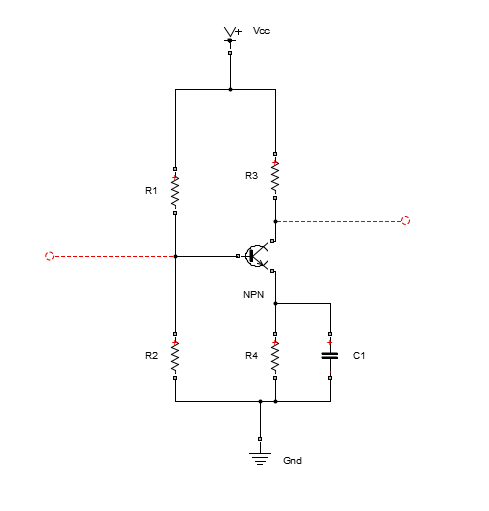
In the BJT amplifier part we need to select the transistor and bias the transistor with appropriate value of resistors.

Using small signal modelling one can derive the requirement for a transistor to be used as an amplifier. The frequency for sustained oscillation in Hz is given by,
\[f=\frac{1}{2\pi \sqrt{6}RC}\]
From the above equation, selecting frequency of oscillator as 20KHz and using R=4.7Kohm we get the value of C as 0.6915uF

One can derive and show that one transistor property for using it as an amplifier for the RF phase shift oscillator circuit is the minimum value of forward current gain of the transistor and is given by,
\[h_{fe}=44.5\]

A transistor with forward current gain of more than 44.5 should work as the amplifier's transistor. We select the 2N3904 transistor. Once we select a transistor, we have to change the parameters of the NPN Transistor. The parameters required for the transistor is seen when it is double clicked.


 Now we have to make appropriate changes so that the transistor behaves like the 2N3904 transistor. The parameters above can be obtained from the 2N3904 transistor datasheet. Part of the datasheet is shown below.


Here, the forward current gain is taken as 100. The output admittance can be found out from the output admittance graph available in the datasheet as shown below.


The output admittance from the graph is 60μmhos.

The collector current at hfe=100 is 10mA and collector-emitter voltage is 1V both obtained from the datasheet. The Vbe voltage is 0.65 and the Ib current can be calculated using the equation,
\[\beta=h_{fe}=\frac{I_c}{I_b}\]
which gives Ib=10mA

The reverse current transfer ratio,BR is the Ideal maximum reverse current gain. This value is not found in transistor datasheets as it is not important when the transistor is biased to operate in the normal active region. Since the transistor will not be operated on the inverse region, we can use the default value of 1.

Altogether the values in the window is shown below,


Next is the the Ohmic Resistance tab which allows to specify the collector, emitter and zero bias base resistances.


In the capacitance tab, we require the junction capacitance and the transit time which are as follows,


This completes the frequency, R and C values and the transistor setting.

Next the biasing resistor values have to be calculated which will be done in the next blog post.

See the earlier posts on oscillator-
Oscillators in communication system
Condition of producing Oscillation from oscillators
How RC Phase Shift Oscillator Works?

Open source Schematic drawing software you should try

It is good to have open source software since they are vendor independent and are for free. There are many Open source/ Freeware Schematic drawing software and Circuit Simulator but the ones below are worth trying out. These application are meant for windows operating system which can be downloaded for free from their website.

LTSpice

LTSpice is a freeware program by Linear Technology. It provides schematic design, simulation and waveform analysis and can be used for analog and digital design and analysis, RF design and simulation, power electronics application. Electronics circuits with transistors, amplifiers, diodes, passive components can be build in the schematics and stimulated to analysis the performance of the circuit. LTSpice supports Transients, DC and AC analysis and parametric analysis. After simulation has been performed circuit netlist can be generated from the schematic and exported to PCB design software of other vendors to create the PCB.


Quite Universal Circuit Simulator(QUCS)

 QUCS is an open source integrated circuit simulator that has schematic editor which means an electronics circuit can be drawn into it. It has also library of electronics components- passive and active components. It supports different kinds of simulation for the designed circuits such as transcient, DC and AC analysis(small and large signal), noise, parametric analysis and also S-parameter analysis. This software can be used for RF and Microwave design, analyze Power Amplifiers, Mixers etc with S-parameter and can be used for plotting Smith charts, perform stability analysis. It also has mathematical equation input feature which allows equation to be used in the simulation analysis.


 Logic Circuit

 Interested in Digital Design and looking for digital logic circuit design program, then try this Logic Circuit. This program is an open source program free to download and use. This program is helpful for testing new microcontroller and microprocessor idea. It has library of digital circuit components such as logic gates(and, or, nand etc) and flip flops that can be drawn into the schematic sheet and perform logic simulation and analysis.


Schematic design software provides an excellent way to learn electronics design.

Sunday, July 13, 2014

Oscillators in Communication System

Oscillator are essential components in communication system. Oscillator generates an output signal with constant amplitude and constant frequency without any input signal. They are used to produce carrier signal onto which message signal are embedded and transmitted over the air to the destination receiver. They are required in all communication system such as AM modulation and circuits, FM and in digital communication system.

Below is a block diagram of a typical transmitter and receiver in which the function of oscillator is illustrated.

In the block diagram the oscillator produces the carrier signal of desired frequency. This carrier signal is mixed with the message signal in the modulator. The modulated signal is sent to the power amplifier which amplifies the signal to the desired power level and gets transmitted over the air the receiver via the antenna.

The basis and principle of oscillator is an amplifier connected with a feedback block. The amplifier can be a non inverting and inverting type. In the non inverting type amplifier, the signal is fed to the positive terminal of the opamp and in inverting opamp the signal is connected to the negative terminal of the opamp. A non-inverting opamp has output that is in phase with the input while an inverting opamp produces ouput signal that is 180 out of phase with the input signal.

A non-inverting opamp requires a positive feedback.  A feedback is said to be a positive one if the phase of its output signal is in the same phase(in phase) with the input signal.

In the above picture the Operational Amplifier and the Feedback Network are the parts of the oscillator. If the amplifier is non inverting then the phase of input and output signal of the amplifier are in phase. The positive feedback provides no phase change and therefore the phase of the input signal of the amplifier and the output of the feedback network are also in phase.

The positive feeedback network feed backs some fraction of output signal Vo back to the input of the amplifier. This is called feedback gain beta and is defined as follows,
\[\beta= \frac{V_f}{V_o}\]     -----(1)

  The open loop gain 'A' is defined as the ratio of Vo to Vin,
 \[A= \frac{V_o}{V_{in}}\]            -----(2)
 The overall gain for the circuit, is called the closed loop gain or the gain with feedback and is given by-
\[A_f= \frac{V_o}{V_s}\]       -----(3)
 The signals Vs, Vin and Vo are related by the equation-
\[V_{in}=V_s+V_f\]    ------(4)
using (1) Vf is,
\[V_f=\beta V_o\]     ------(5)
Using (5) in (4) we get,
\[V_{in}=V_s+\beta V_o\]
or, \[V_s=V_{in}-\beta V_o\]    ----(6)
using (6) in (3) we get,
 \[A_f= \frac{V_0}{V_{in}-\beta V_o}\]   ----(7)
Dividing RHS of (7) by Vin and using (2) we get relation between Af and A as follows,
 \[A_f= \frac{A}{1-\beta A}\]

This is a relation between the closed loop gain and open loop gain.


The condition of producing oscillation in oscillator

To make an oscillator requires amplifiers or Opamp. The input signal to opamp can be connected in non-inverting and inverting terminal. A non-inverting amplifier produces no phase shift between the signal at the input and output. But an inverting amplifier produces a phase shift of 180 degree.

When an inverting operational amplifier is used as an oscillator, the feedback network must produce a phase shift of 180 degree so that the feed backed signal is again in phase with the original input signal. This ensures positive feedback as required for the oscillation.

The figure below shows a circuit drawn in Matlab 2014 and in the figure the input signal Vs is connected to the negative terminal of the opamp so the signal Vo coming out operational amplifier is has a phase which is 180 degree away from the input signal Vs.

 The feedback network provides adds a phase shift of 180 degree to the signal Vo and the ouput signal Vf is then in phase with the signal Vs.

The condition for the sustained oscillation is that the feed back signal Vf should act as Vs. In other words, the amplifier pluse the feedback network should produce signal with only Vf without Vs.

Now,
  \[A=\frac{V_o}{V_{in}}\]   ----(1)
therefore,
\[V_o=AV_{in}\]      ----(2)
Similarly, Vf is,
\[V_f=\beta V_{o}\]   ---(3)
and placing Vo from (2) into (3) gives,
\[V_f=A\beta V_{in}\]    ---(4)
And the oscillation should happen with the input signal Vs when Vs=Vf which gives,
\[|A\beta|=1\]    ----(5)

So in order to produce sustained oscillation without the external signal we require-
(1) that the total phase shift around the loop should be 0 or 360 degree
(2) the product of open loop gain and beta should be 1 as per the equation (5)

See the earlier post oscillator in communication system

How RC Phase Shift Oscillator Works?

Oscillator is made up of amplifier and a feedback network. When the amplifier used is an opamp then the input signal can be connected to the inverting and non-inverting terminal of the operational amplifier. If the input signal is connected to the inverting terminal then a 180 phase shift must be produced by the feedback network so that the input signal and the feed backed signal are in phase.

The application of oscillator in communication system and condition for oscillation was introduced and derived in earlier post. This post is about how the RC phase shift oscillator works.

Consider the RC circuit drawn in Matlab 2014 simulink/ Simscape as shown below

In this circuit by using appropriate values for the capacitor and resistor we can produce desired phase shift between the input signal Vin and the output voltage signal Vout. The phase shift difference is given by the formula-
\[\phi=\tan^{-1}(\frac{X_c}{R})\]
where, Xc is the capacitive reactance of the capacitor and R is the resistance of the resistor
and, \[X_c=\frac{1}{2\pi fC}\]
where C is the capacitance of the capacitor

If we were to produce a 60 degree phase shift between Vin and Vout(the voltage across resistor) then we have tan60=1.732 and using R=1 ohm, we get Xc=1.732. This gives C value of 0.02758F when frequency of the input signal is taken as 10Hz.

Using these values the circuit above can be stimulated in Simscape to verify the phase shift graphically. For the simulation to work few parts have to be added to the above circuit.

The scope shows the waveform of the input signal(upper waveform) and the output signal(lower)-

To view the signal together in the same window we can use the mux.


This shows that there is a phase shift of 60 degree between the input and output signal.

If such RC circuit is used 3 times connected in a ladder fashion as shown below we get a total phase shift of 180.

The waveform of the input and output signal of this RC ladder circuit is shown below-

This graph shows 180 degree phase shift between the input signal(Vin) and the output signal (Vout) of the first circuit above. Also there is decrease in magnitude of the output signal.

Hence when this 3 section RC circuit is used in the feedback network as it produces the required 180 phase shift. Below the structure of the oscillator with feedback network.

The content of the feedback network block is the RC network-

The operational amplifier in the above circuit can be replaced by amplifier designed with transistor biased in the linear region of operation.

An oscillator with transistor amplifier and RC feedback network would look something like this-


See also matlab 2014 download and matlab tutorials on this blog.

What's Inside a Bluetooth Headset


In this post we will learn what's inside a Bluetooth headset gadget and also know how to hack it for using it for other useful personalized applications.

The world is going digital at a rapid pace and advanced concepts such as Bluetooth are quickly replacing the other traditional form of technologies.

What's Bluetooth? It's another wireless transmission technology used for exchanging a wide variety of data in a precoded form over short distances via devices that may be compatible to cell phone, smart phones, laptops, PCs, Wi-Fi systems etc.

Basically Bluetooth also incorporates Rf waves but in a digitally coded form, quite unlike to the traditional FM or AM concepts.

It's an advanced and enhanced form of wireless technology that is designed to be able to connect with many compatible devices at a time without encountering synchronization problems or hurdles.

A Bluetooth headset is another related device which is designed to exchange (transmit and receive) data using Bluetooth technology across similar above mentioned compatible devices.

It's a very interesting RF device which could be hacked by an hobbyist in order to make it work for any desired customized application. For example we can use the headset device to make our home theaters systems completely wireless with crystal clear responses, or may be we can use it for controlling a few of the appliances across the rooms in our house or apartment.

Opening a Bluetooth Headset gadget

In order to experiment with a Bluetooth Headset you could probably buy a typical type that's shown below or if you already have one you can use it for the discussed hacking procedures.


To break it open you can use a screw driver as shown in the picture below. However you will need to maintain extreme dexterity and care while operating the gadget making sure you don't damage the internal circuitry.


Once the cover is removed, you would come across another plastic shielding which you can identically remove using the tip of your screw driver.


Once the inner protection shield is peeled of, the actual PCB with various components would pop out from the shell as shown below.

 In this position the few important things that would become visible are: two wires running toward a small speaker, two wires towards an in built MIC, an USB connector and an attached battery. See below for the details


For getting the entire assembly out of the box, you could probably go ahead and remove the speaker and the Mic from their respective locations, in order to study them in-depth.


The MIC could be found hidden inside a metallic clipping which could be pulled out with some careful effort.

Once removed.... the MIC, the speaker and the PCB with all the associated components could be studied in details as shown in the following figure:


Another important area we would be interested within the circuit is the USB socket, since its the input which receives all the data, and also the battery for getting well versed regarding what's inside a typical Bluetooth headset.


The battery is a 3.7V Li-ion, 120mAH battery, as may be witnessed in the following image:


OK that's it, now we exactly know all that's inside a Bluetooth headset gear, and it's time to learn a few of the simple hacking techniques that would enable us to use any Bluetooth headset unit for performing the intended operations.

The next post will explain how to hack a Bluetooth Headset for other personalized implementations such as for remotely operating an appliance, as a spy bug, and audio related applications such as for making wireless speaker systems and home theater systems.