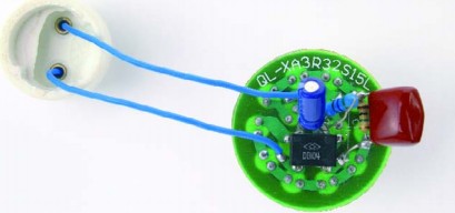
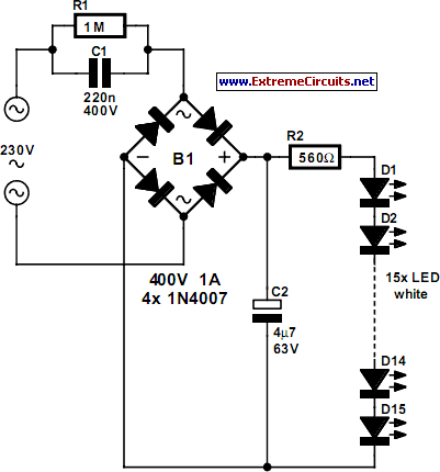
Did it ever occur to you that an array of white LEDs can be used as a small lamp for the living room? If not, read on. LED lamps are available ready-made, look exactly the same as standard halogen lamps and can be fitted in a standard 230-V light fitting. We opened one, and as expected, a capacitor has been used to drop the voltage from 230 V to the voltage suitable for the LEDs. This method is cheaper and smaller compared to using a transformer. The lamp uses only 1 watt and therefore also gives off less light than, say, a 20 W halogen lamp. The light is also somewhat bluer. The circuit operates in the following manner: C1 behaves as a voltage dropping ‘resistor’ and ensures that the current is not too high (about 12 mA).

The bridge rectifier turns the AC voltage into a DC voltage. LEDs can only operate from a DC voltage. They will even fail when the negative voltage is greater then 5 V. The electrolytic capacitor has a double function: it ensures that there is sufficient voltage to light the LEDs when the mains voltage is less than the forward voltage of the LEDs and it takes care of the inrush current peak that occurs when the mains is switched on. This current pulse could otherwise damage the LEDs. Then there is the 560-ohm resistor, it ensures that the current through the LED is more constant and therefore the light output is more uniform.

There is a voltage drop of 6.7 V across the 560-Ω resistor, that is, 12 mA flows through the LEDs. This is a safe value. The total voltage drop across the LEDs is therefore 15 LEDs times 3 V or about 45 V. The voltage across the electrolytic capacitor is a little more than 52V. To understand how C1 functions, we can calculate the impedance (that is, resistance to AC voltage) as follows: 1/(2π·f·C), or: 1/ (2·3.14·50·220·10-9)= 14k4. When we multiply this with 12 mA, we get a voltage drop across the capacitor of 173 V. This works quite well, since the 173-V capacitor voltage plus the 52-V LED voltage equals 225 V. Close enough to the mains voltage, which is officially 230 V.
The bridge rectifier turns the AC voltage into a DC voltage. LEDs can only operate from a DC voltage. They will even fail when the negative voltage is greater then 5 V. The electrolytic capacitor has a double function: it ensures that there is sufficient voltage to light the LEDs when the mains voltage is less than the forward voltage of the LEDs and it takes care of the inrush current peak that occurs when the mains is switched on. This current pulse could otherwise damage the LEDs. Then there is the 560-ohm resistor, it ensures that the current through the LED is more constant and therefore the light output is more uniform.

There is a voltage drop of 6.7 V across the 560-Ω resistor, that is, 12 mA flows through the LEDs. This is a safe value. The total voltage drop across the LEDs is therefore 15 LEDs times 3 V or about 45 V. The voltage across the electrolytic capacitor is a little more than 52V. To understand how C1 functions, we can calculate the impedance (that is, resistance to AC voltage) as follows: 1/(2π·f·C), or: 1/ (2·3.14·50·220·10-9)= 14k4. When we multiply this with 12 mA, we get a voltage drop across the capacitor of 173 V. This works quite well, since the 173-V capacitor voltage plus the 52-V LED voltage equals 225 V. Close enough to the mains voltage, which is officially 230 V.
Circuit diagram:
Moreover, the latter calculation is not very accurate because the mains voltage is in practice not quite sinusoidal. Furthermore, the mains voltage from which 50-V DC has been removed is far from sinusoidal. Finally, if you need lots of white LEDs then it is worth considering buying one of these lamps and smashing the bulb with a hammer (with a cloth or bag around the bulb to prevent flying glass!) and salvaging the LEDs from it. This can be much cheaper than buying individual LEDs…

