What is an active antenna?
An active antenna is an receiver front end design technique in which an active FET transistor amplifier is placed very near to the actual physical antenna plus other supporting amplifying stages usually made of bipolar transistors being placed following the FET amplifier. Active antenna design provides large range of frequency selection and are used in the receivers.
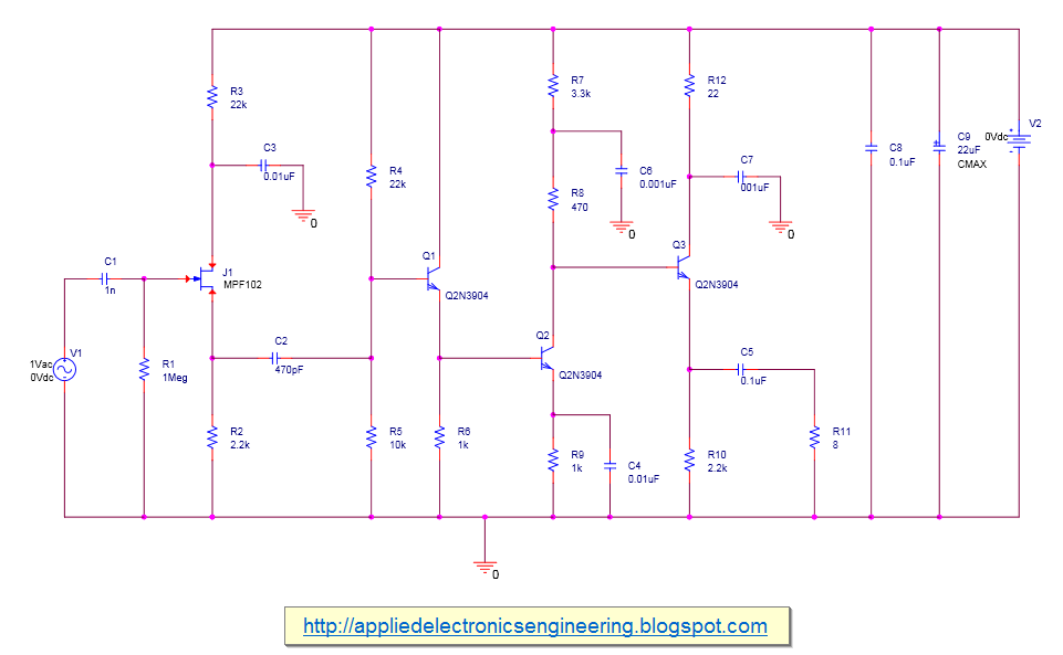
Below is a an active antenna design schematic drawn in Orcad Capture.
Note: the power supply is 9V battery not 0V in the above schematic
In the above schematic, the V1 a.c source is modeled as antenna. The J1 MPF102 is the FET transistors that is very close to the antenna. C1 is the decoupling capacitor to stop the input frequencies flowing back to the source. The transistors 2N3904 forms further amplifying stages. See this active antenna amplifier circuit design for more explanation of this. In the circuit above, resistor R11 is the load. Other resistors are for biasing the transistors and the capacitors are decoupling capacitors and bypass capacitors. See transistor biasing tutorial for this.
An AC sweep analysis from 100KHz to 50MHz was performed on the circuit. The Power Gain plot is shown below-
The antenna with the Power Amplifiers are used in TV, audio circuits and in communication circuit. They are many ways one can classify the different types of power amplifier. One is based on frequency of operation, audio amplifier or RF amplifier, another is based on duty cycle, that is how long the output signal is available over the period of input signal.


No comments:
Post a Comment