Saturday, September 28, 2013
Matching the supply line to the antenna output of transmitter
Thursday, September 26, 2013
Amateur G5RV wire antenna
Amateur G5RV wire antenna in the picture with a size of 31 meters, it is the transition between the antenna option with long arms and a 54-meter antenna with an arm length of 27 meters. By wire antenna connected two-wire power supply with an impedance of 300 ohms (balun). Length of the power line should be 12.90 meters. This line acts as a power transformer. Towards the bottom of the feed point of the transformer is connected coaxial cable (Figure).
In the range of 28 MHz each half G5RV wire antenna has a length 3L / 2. Diagram of a shape of the antenna length 3L. In-phase excitation power gain compared to a conventional dipole is 1.8. In this range, the antenna G5RV works well. Since the length of the line is transforming 5L / 4, the wire antenna is in excellent agreement with the coaxial cable. At the points of "BB" impedance of about 60 ohms.
In the range of 21 MHz antenna length is slightly longer wavelength (L) of the range and reach the transformer is also a little longer than 3L / 4 matching any worse. Sizes do not allow you to work in a resonant mode, in spite of this antenna has a gain over a dipole is 1.8 dB, due to the fact that half the vibrator excited in phase. Diagram of the wire antenna in the same range as the two wave vibrator.
In the range of 14 MHz antenna matching is even worse than 21 MHz. At the points of "AA" very little resistance from the fact that the antenna has a size of 1.5L and is approximately 70 ohms. At these points there is a maximum current. Transforming line transforms the antenna impedance (70 ohms) to 200 ohms at points "BB". It is clear that such resistance is not suitable for connecting a coaxial cable with an impedance of 50 ohms ... 75. Reinforcement wire antenna in the range of about 2 - 2.2 dB.
In the range of 7 MHz G5RV wire antenna has a length 3L / 4 and the input impedance of 600 ohms. Length of transforming the line has 300 ohms resistance and the length of the 0.3L, as a result of the partial transformation of the 600 ohm resistance at the points of "AA" to the point "BB" is obtained impedance 150 ohm. Since the directional properties of the antenna wire in this range are similar pattern in a half-wave dipole and the win is no gain.
In the range of 3.6 MHz is a resonance antenna of its length in this range is 0.36 ... 0.47L. Antenna impedance is 150 ohms, the length of the transformer is equal to 0.15 ... 0.16L at points "BB" resistance is 100 ohm. In this range, the directional properties of even worse and the winning wire antenna gain, however.
From the above it follows that the written wire antenna (classical) English G5RV amateur radio should be used in conjunction with the tuner (for the transceiver). Changing the length of the line transformer and its impedance leads to improved coordination in some ranges and a deterioration in others.
A Practical Antenna for 160 Metres
Original article published by G3YCC
"This aerial is one I have used for top band (160 metres) - it was suggested to me by Alan G4ERZ, also of Hull.
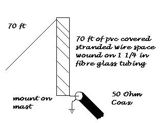
It consists of 140 feet of insulated wire, the first half of which (70 feet) is space wound on an insulated tube.
- I used glass fibre tubing which was to hand, but PVC may be used also.
- My tube is 1 1/2 inches in diameter and about 5 feet 6 inches long.
- The turns are about 0.5 inches apart.
- The other 70 feet of wire acts as a loading wire and slope down from the top of the coil to near ground level.
- The system is coax fed to the base of the coil, with the shield or braiding going to earth.
It appears to work very well, apparently giving some horizontal and vertical polarisation.
One great advantage is the system can be tuned without having to lower the mast - by pruning the loading wire to resonate on the required part of the band.
Bandwidth is also good - mine is about 30 kHz either side of resonance.
I found the MFJ Antenna Analyzer MFJ-259 invaluable for this project, as well as many other experimental systems. Ensuring an efficient earth system will add to the effectiveness of the aerial I still have to improve my earth system, currently it consists of two 140 ft radials and connections to some buried guys stays.
Alan, G4ERZ, has a far more elaborate and efficient ground and his results prove what we all know - the ground (or earth system) is all important. He is a tremendous signal on 160 DX wise. He still gets the same band width as I do, though. I have worked a few DX stations with it since erecting it only a short while ago, and I think it has a lot to offer, especially for those of us blessed with relatively small gardens."
A short dipole for 80 meters
The antenna above has been described by Nadisha, 4S7NR and may be of interest to anyone wishing to get on 80M (3.5MHz) that have limited space available.
L1 is 12 feet. L2 also is 12 feet and the overall length is 48 feet.
The two loading coils are described as 67.83uH and can consist of 104 turns of insulated wire, wound over 3.5 inches. The coil diameter is not stated however. Maybe it will be a case for experimentation here.
An Inverted L for stealth with low(ish) visual impact
With a small back garden there is no way that I could accommodate an aerial for the 160m band that would be anything approaching full size. A full size dipole would be about 65 metres long and would need to be mounted at a very good height to be at its most effective. A full size vertical 1/4 wave would be about 37.5 meters tall. Impossible! Bending a 1/4 wave wire into an inverted L would still result in a very long wire - say 10 metres vertically and 27.5 metres horizontally. Still too large.
Full size top band antennas are big, far too big for my small plot, so I have tried a few different shortened 160m aerials. I really would prefer to use a balanced dipole not only for the radiation efficiency, but just as importantly for the lower noise on receive - like a ground mounted vertical aerial an inverted L can be rather noisy on RX. However I have to settle for a compromise, so shown in the drawings and photographs below is my current top band aerial, along with some previous experiments and ideas further down the page.
This incarnation of my Top Band aerial takes two forms. A compact Inverted L and, in its lower position, a less conspicuous sloping wire, shown below:
General layout of Top Band Aerial with fibreglass pole retracted to a height of 2 metres
Wire lengths are approximate: Inductor 5cm dia with approx 40 turns of 0.9mm e.c.w.