Saturday, December 31, 2011

How to Make a robot ( four wheels and attack on enemy) Here we make a Robot X4-37

Hello Friends today i going to explain you that how to make a simple robot. first of all we have to know about the robot, that what is it ?A robot is a mechanical or virtual intelligent agent that can perform tasks automatically or with guidance, typically by remote control. In practice a robot is usually an electro-mechanical machine that is guided by computer and electronic programming. Robots can be autonomous, semi-autonomous or remotely controlled. Robots range from humanoids such as ASIMO and TOPIO to Nano robots, Swarm robots, Industrial robots, military robots, mobile and servicing robots. By mimicking a lifelike appearance or automating movements, a robot may convey a sense that it has intent or agency of its own. The branch of technology that deals with robots is robotics.

Now we will start form the low level. Now we will make a simple robot which can perform the basic task like forward, backward, turn left ,turn right ,and one additional function like any weapon or a work.

We are going to start from  a robot know as the X4-37 . which is generally used in the college level competition of fight .The X4-37 is consist of a wooden cheeses( which can be main base of the robot on which all the part are fixed), 4 Hi-Speed and Hi-Torque DC motor, 4 rubber wheels, a DC source , remote control,wires and any weapon of function .

 Here is a model of  X4-37 


The all required things can easily available in the market or in local area .


Now we start form the cheeses .It is maid up or ply-wooden . which is cut in the required shape and size. as per our required work and the criteria .we can choose the strength of the ply depends on the material. now here we taken the size of the ply  25 x 35 cm as shown in the picture bellow. And the holes are maid as per the fixing of the motor's size and the length .


A upper side
  
A lower side 


Next we required the Motors , wheels and a Dc source . we used a  150 rpm 4-motors ,4-rubber wheels and a 12-volts Dc source . as shown in picture below .


and for your clearance
   
Nut bolts and clip for the clipping or fixing of the motor with the wooden ply. 


Sunday, June 26, 2011

Build very low cost FM transmitter, use your TV antenna and transmit upto 4km range!!

 Here is the specification of the transmitter


1. No. of stage: 4
2. Frequency of operation: About 100MHz
3. Antenna type: Folded 300 ohms dipole.
4. Range obtained in free space: Up to 4km with dipole antenna 30 feet above ground level. More   range with yagi antenna.

Fig: Circuit diagram of the Transmitter


Brief Description:
The transmitter is built on a Printed Circuit Board. This board uses track inductor for L1, L2 and part of L3. The section built around Q1 is the oscillator section. Oscillation frequency is determined by L1, C4 & C5 which forms the tank. Actually C5 is the feedback capacitor. This is required to sustain oscillation. This also influence the operation of tank formed by L1 & C4. Modulation is directly applied to the base of Q1 via C2. A microphone is connected here to serve this purpose. You can alternately feed direct audio here after disconnecting the microphone biasing resistor R1. Q2, Q3 & Q4 gradually raises the output power up to the desired level.
As most of the inductors are PCB etched, there is practically very little frequency drift provided you use a highly regulated and ripple free power supply.
RF output from the transmitter is taken from the junction of C11 & C12. This is unbalanced output of around 75 ohms impedance. But a folded dipole is a balanced type antenna of around 300 ohms impedance. So we need to use a 'BALanced to UNbalanced transformer' or 'BALUN'. A 1:4 type BALUN is employed here for this purpose. Antenna connection is taken from this BALUN via a 300 ohms flat parallel feeder cable commonly used in television to receive terrestrial broadcast. No coaxia is used to feed antenna. This saves cost. Also a parallel feeder cable provides much less signal loss compared to a coaxial.

 Click 'Read More" to see details with pictures

Design of BALUN
The BALUN is made using a two-hole binocular ferrite bead as shown above. You need to use parallel insulated twin wire to construct this. This wire is commonly used to wind TV BALUN transformer. If you want to get rid of this, then buy a ready-made TV BALUN that is generally used at the back of your television set for interfacing with feeder wire.
If you prefer to build this yourself, the circuit diagram is given above. You need to carefully construct it keeping in mind about the 'sense' & 'direction' of turns. See there are four coils. Two coils in the upper section, which are red and blue, required to be wound on left side of the BALUN and the remaining two (blue & red) in the lower half to be wound on right side. Connection marked 'A' and 'B' at the left side of the circuit is reqired to be connected to the PCB at the shown point. As dipole antenna is balanced type, so you need not to worry about its connection.


 PCB design details
The transmitter is built on a single sided PCB. As mentioned earlier, this PCB has a number of etched inductors. For this reason, you need to very carefully construct the PCB as mentioned below.


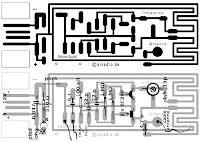
The above drawing is the copper side and below shown is the component mounting plan.


In the copper side view, you can see that there are three track etched inductors that resembles 'RCL' Every corner and track width/length are calculated and then they are drawn so that each 'RCL' section becomes an inductor of required value. Never play with this; otherwise, optimum result could not be achieved.
You need to use a laser printer or a high quality printer to get a printout of the drawings. First, save the picture to disk. Now try to print it from such a software which permits you to control print size. 'Paint Shop Pro' is such a software. Of course you can use any other software. Print the drawing so that copper side drawing is exactly 59mm X 59mm. Few trial will give you the perfect print. Now construct the PCB using 'Photo-etching' method so that all the tracks becomes exactly same as you are now seeing. Now drill the PCB carefully. The PCB is now ready to populate.
Start population according to the component mounting plan. You can also get a true size copy of this plan printed and glued to the PCB. This will help you work fast.Part of L3 is required to be constructed. This is described in parts list.
Please note that in the picture of the transmitter kit, capacitor C1 & C10 are not mounted by mistake and the kit is filmed. Please add these two capacitors. Try to keep all component leads as short as possible.
Now you need to design the dipole antenna to use with the kit.

N.B: Believe it or not, a 2N2369 from Philips, used in the final power amplifier section, can give this much of range. 


Detailed Parts List:

RESISTORS
R1 - 22K
R2 - 100K
R3, R7, R9 - 1K
R4, R8 - 100E
R5 - 390E
R6 - 330E
R10 - 15E
R11 - 10K
CAPACITORS
C1, C3, C10 - 1n
C2 - 100n
C4,C8,C9 - 47pF
C5, C11 - 10pF
C6 - 100uF/25V Electrolytic
C7 - 100pF
C12 - 3pF
TRANSISTORS
Q1, Q2, Q3 - BC548
Q4 - PN2369 (Plastic casing) or 2N2369 (Metal casing)
MISC.
L3 - 7 turns, 22SWG wire, 3mm ID, Close wound, Air core.
Two hole binocular BALUN core, BALUN wire, 300 ohms TV feeder wire,
JP1 to JP5 - All jumper wires.
This completes the Project. Please mail me with your feedback. It will really encourage me to give you more & more project like this.
 

Success story, making of my FM Transmitter.

I've tried to build (make) my own Fm transmitter from the very beginning of my boyhood but failed failed and failed. My first successful Fm transmitter was aired in 2001 when i was a student of class 12. After a long run of  4 years from class 9.

here i'll show you my recent 10 watt Fm transmitter testing circuit (battery powered exciter only due to security matter) and finally assembled cabinet (AC powered). 


 Transmitter after assambled

 Click "Read More" to see the other photos........


 close view


Heart of FM transmitter (the exciter)

Friday, June 17, 2011

ANTENNA DESIGN FOR FM TRANSMITTE

 ANTENNA DESIGN

There are two types of antenna for FM TRANSMITTE
1. Ground pole Antenna    
2. Half-Wave Dipole Antenna
A ready made GP Antenna. 


1. Ground pole Antenna(GP)

This Antenna is most widely used all over the world. For example, when you see a police car it has a transmitter with Ground Pole Antenna The body of car serves as ground). It accepts load from 50 ohm source and has larger power output than Half-Wave Dipole Antenna.


Frequency
Radiator - B
Radials - A
108MHZ
660
693
104MHz
684
720
100MHz
713
749
90MHz
792
819


 2. Half-Wave Dipole Antenna Or Open Dipole Antenna

It accepts load from 75 ohm source and has much smaller power output than Ground Pole Antenna. Use this antenna only when you don't have GP Antenna.
Construction: Two aluminum rods ,each of length "L" in meters are joined together through an insulator as shown in fig. From center, 75 ohm cable is feeded just like ordinary TV antenna.


I'll discuss the design, calculation of length, wire to be used and set-up details of FM TRANSMITTER Antenna very soon in this blog. so stay tuned.


Thursday, June 16, 2011

1 Watt simple FM Transmitter with 1-2 km range!

1 Watt FM Transmitter


This is simple 1 Watt FM Transmitter circuit. This circuit will be able to cover 1-2 KM range with a single pole antenna of 20 feet! 


Click on picture  to view the large size

Descriptions:
P1 act as condenser microphone volume level. For FM, coil will be small. Use thin gauge enamel magnet wire. the diameter of coil will be a couple mm: use ink tube from pen to form, and try 8-12 turns. Small inductance coils make for much guess work.

Components/parts  List:

R1=220K
R2=4.7K
R3,R4=10K          
R5=100ohm
C1,C2=4.7uF Electrolytic
C3,C4=1nF
C5=2-15pF
C6=3.3pF
Q1=BC547C
Q2=2N2219A
P1=25K MIC=Electret Condenser Type


Construction of Air Core Coil for FM transmitters

Just follow the steps as shown in the following pictures to make the air core coil for your Fm transmitter


                           Click  "Read More" to view details


 1. Select magnet wire of specific gauge as described in circuit (buy from motor/fan repairing shop).


 2. wound (round up) the wire on a pencil, pen or screw driver of correct diameter as stated in circuit diagram.


 3. don't make any half turn without any guide from your circuit text. Remove the pencil, pen or screw driver .


 4. Your Coil is almost ready, Cut the extra length of leg's and solder the both leg (pins) of your coil. try to keep the length of leg as minimum as possible. it'll give stability of your frequency.


 5. Shrink or expand the coil as the required length as stated in your desired circuit text.


 6. Here is your coil


Simpliest 2 watt FM transmitter with PCB and details


 USE DIPOLE ANTENNA FOR MAXIMUM RANGE (COULD BE UP TO 10 KM IN GOOD WEATHER). TUNE BETWEEN 88-108 MHz WITH C5. BB-204 COULD BE REPLACED WITH CONVENTIONAL LED (BIG) WITH REVERSE BIAS (NO LIGHT GIVEN IN CORRECT POLARITY). 9V POWER FOR 2KM WITH GOOD SOUND QUALITY AND GRADUALLY UP TO 18V FOR 10 KM RANGE WITH POOR QUALITY OF SOUND.  BEST OF LUCK. 


www.fmradio-transmitter.blogspot.com

USB FM Transmitter Circuit for PC and Laptop

Here's a small FM transmitter ciruit for your desktop or laptop to enjoy the movie and music from a distance. This FM transmitter, which is powered by USB, recovers output on your computer or your MP3 player to the relay on the tape FM (frequency 108 MHz). For Assemblying this FM transmitter kit, an electronics hobbyist will have built in about 30 minutes.


FM Transmitter Construction
It is not necessary to drill the transmitter PCB. All components will be soldered to the plate with their legs folded.


The two transistors and the LEDs are polarized:
The transistor has a flat side, the LED a foot longer than the other is the anode (A), the other is the cathode (K). The audio cable (minijack) must be transformed from a stereo cable into a cable.


Mono Sound:
Soldering together the white and red cables, leaving aside the yellow cable (mass). The frequency setting will be turning the variable capacitor gently with a screwdriver or thin cardboard but rigid.


FM Transmitter Parts List
* 1 Ohm resistor 510 (green - brown - brown)
* 100 resistor 1 kOhm (brown - black - yellow)
* 1 MOhm resistors (brown - black - green)
* 1 capacitor 0.1 uF (0.1)
* 1 nF capacitor 47 (0.047)
* 1 capacitor 4.7 pF (479)
* 2 pF capacitors 22 (22)
* 1 variable capacitor 1.5 pF ... 15
* 2 transistor BF 246 (F246A)
* 1 red LED
* 1 audio cable (minijack)

Tuesday, May 17, 2011

Build a Wi-Fi antenna using household materials


Who'd have thought that a toilet-brush holder, of all things, would turn out to be an excellent Wi-Fi antenna? The lesson is that you can achieve great results for little expense - and half an hour's work.The range of a WiFi router can be considerably extended simply by connecting a directional antenna. Standard omni-directional stub antennas are at the lower end of the performance scale, and they quickly come up against their limits when you need to give your own home better coverage, provide your neighbour with DSL, or pick up as many radio networks as possible while war driving.If the access point is three rooms further on, or even in the house on the other side of the road, you need a directional antenna. If you have to make a connection to your nearest DSL-equipped acquaintance at the other end of the village street, or to bridge even longer radio links to reach the free radio[1] node in the next block but one, you may even require two directional antennas.

Neighbourhood WiFi routers with omni-directional aerials are in any case the worst sources of interference in a city. A single block of flats can easily contain over ten wireless networks, all chattering away simultaneously. Mutual interference is inevitable, with the result that range and connection stability are drastically reduced.Replacing just one of two antennas at the base station can be a way of improving WiFi coverage, for example, down to the bottom of the garden. The near zone is served by the remaining stub. All current WiFi modules automatically use the most suitable antenna for each client, a process called antenna diversity. Even with models having only one external antenna, it's worth having a look inside the casing. Usually, a tiny socket for the second antenna is fitted on the WiFi module. Depending on the manufacturer, this type of plug is called U.FL or Ipex. The connection can easily be led out through a ventilation slot with a short adaptor cable ("pigtail"). On some WiFi notebook cards and USB sticks, there is also an antenna plug, and a look at the data sheet will tell you its type – normally SMA or RPSMA.

The simply made tin-can antenna, with the dimensions given here, is suitable for base stations and for clients who transmit on 2.4 GHz in accordance with the IEEE 802.11b and 802.11g standards. 802.11a uses the 5-GHz band, requiring different antenna dimensions. The necessary background for a recalculation is given in an article on building tin-can radio antenna (Building a Wi-Fi Antenna Out of a Tin Can) [2]

Very recent base stations that comply with the draft standard 802.11n also use the 2.4 GHz band. But they automatically use a number of methods to combine their antennas for optimal range and speed. However, this only works if the antennas have the characteristics expected by the WiFi chipset.


http://www.h-online.com/features/Build-a-Wi-Fi-radio-relay-using-household-materials-747382.html?view=print

Hex Beam antenna


I am currently looking at building a Hexx wire beam antenna. Due to space restrictions and various things w.r.t antennas in New Zealand I do think that this antenna can work for me.
I had a browse around and found a couple of websites referring to hexx beams and how to make it.It seems fairly easy and with a 5 band version all on one feed line it is well worth investigating.
Here is a picture of a typical Hexx beam:


So, how should I start,I managed to get a aluminium base plate at a scrap metal shop for a good price, Picked up some old PVC 20mm tube in 2 m lenghts and have wire I collected over the years.I made the PVC into 2m lengths to accommodate a 3 band antenna which will host 10m / 12m / 15m (28mhz / 24mhz / 21mhz).Now I made the aluminium base plate into a HEXX shape. With my thinking cap on I managed to make a Hexx shape. What a story if you do not have a compass.

The Wire needs to be added and this is what it should look like from above once completed.


I will post pictures as I progress so be sure to check back to follow my progress.

http://zs6lw.blogspot.com/2009/11/hexx-beam-antenna.html

MOSFET-BASED PREAMPLIFIER FOR FM RADIO Project


FM transmissions can be received within a range of 40 km. If you are in fringe areas, you may get a very weak signal. FM DXing refers to hearing distant stations (1500 km or more) on the FM band (88-108 MHz). The term ‘DX’ is borrowed from amateur radio operators. It means ‘distance unknown’; ‘D’ stands for ‘distance’ and ‘X’ stands for ‘unknown.’ For an FM receiver lacking gain, or having a poor signal-to-noise ratio, using an external preamplifier improves the signal level.

The dual-gate MOSFET preamplifier circuit shown in Fig. 1 gives an excellent gain of about 18 dB. It costs less and is simple to design. Field-effect transistors (FETs) are superior to bipolar transistors in many applications as these have a much higher gain—approaching that of a vacuum tube. These are classified into junction FETs and MOSFETs. On comparing the FETs with a vacuum tube, the gate implies the grid, the source implies the cathode, and the drain implies the plate.In a transistor, the base implies the grid, the emitter implies the source, and the collector implies the drain. In dual-gate FETs, gate 1 is the signal gate and gate 2 is the control gate. The gates are effectively in series, making it easy to control the dynamic range of the device by varying the bias on gate 2. The MOSFET is more flexible because it can be controlled by a positive or negative voltage at gate 2. The resistance between the gate and rest of the device is extremely high because these are separated by a thin dielectric layer. Thus the MOSFET has an extremely high input impedance. Dual-gate MOSFETs (DG MOSFETs) are very popular among radio amateurs. These are being used in IF amplifiers, mixers, and preamplifiers in HF-VHF transceivers.

The isolation between the gates (G1 and G2) is relatively high in mixer applications. This reduces oscillator pulling and radiation. The oscillator pulling is troublesome particularly in shortwave communications. It is a characteristic in many unsophisticated frequency-changer stages, where the incoming signal, if large, pulls the oscillator frequency slightly off the frequency set by the tuning knob and towards a frequency favourable to the (large) incoming signal. A DG MOSFET can also be used for automatic gain control in RF amplifiers. DG MOSFET BF966S is an n-channel depletion-type MOSFET that is used for general-purpose FM and VHF applications.


In this configuration, it is used for FM radio band. The quadratic input characteristic of the FET input stage gives better results than the exponential characteristic of a bipolar transistor. Gate 1 is meant for input and gate 2 is for gain control. The input from the antenna is fed to gate G1 via C1 and L1. Trimmer VC1 is used to tune and select the input frequencies. Capacitor C4 (100 kpF) at the gain control electrode (gate 2) decouples any variation in G2 voltage at radio frequencies to maintain constant gain. Set preset VR (47k) to adjust the gain or connect a fixed resistor for fixed gain. The output of the circuit is obtained via capacitor C5 and fed to the FM receiver amplifier.

For indoor use, connect a ¼- wavelength whip antenna, ½-wavelength 1.5m wire antenna, or any other indoor antenna set-up with this circuit. You may use a 9V battery without the transformer and diode 1N4007, or any 6V-12V power supply to power the circuit (refer Fig. 1). The RF output can be taken directly through capacitor C5. For an improved input and output impedance, change C1 from 1 kpF to 22 pF and C5 from 1 kpF to 100 kpF. For outdoor use at top mast, like a TV booster, connect the C5 output to the power supply unit (PSU) line. Use RG58U/ RG11 or RG174 cable for feeding the power supply to the receiver amplifier. The PSU for the circuit is the same as that of a TV booster. For TV boosters, two types of mountings are employed: The fixed tuned booster is mounted on the mast of the antenna. The tunable booster consisting of the PSU is placed near the TV set for gain control of various TV channels. (For details, refer ‘High-Gain 4-Stage TV Booster’ on page 72 of Electronics Projects Vol. 8.) Mount the DG MOSFET BF966S at the solder side of the PCB to keep parasitic capacitance as small as possible. Use an epoxy PCB. After soldering, clean the PCB with isopropyl alcohol. Use a suitable


enclosure for the circuit. All component leads must be small. Avoid shambled wiring to prevent poor gain or self oscillations. Connecting a single-element cubical quad antenna to the circuit results in ‘Open Sesam’ for DXing.You can use a folded dipole or any other antenna. However, an excellent performance is obtained with a cubical quad antenna (refer Fig. 2) and Sangean ATS- 803 world-band receiver. In an amplifier, FET is immune to strong signal overloading. It produces less cross-modulation than a conventional transistor having negative temperature coefficient, doesn’t succumb to thermal runaway at high frequencies, and decreases noise. In VHF and UHF, the MOSFET produces less noise and is comparable with JFETs. DG FETs reduce the feedback capacitance as well as the noise power coupled to the gate from the channel, giving stable unneutralised power gain for wide-band applications. This circuit can be used for other frequency bands by changing the inputand the output LC networks. The table here gives details of the network components for DXing of stations at various frequency bands.

Saturday, April 16, 2011

Coilless FM transmitter !

 If you are in the problem to make perfect coils for FM Transmitter then this is your time to go on..... See this coil less and easy FM Transmitter.


The RF oscillator using the inverter N2 and 10.7Mhz ceramic filter is driving the parallel combination of N4 to N6 through N3.


Since these inverters are in parallel the output impedance will be low so that it can directly drive an aerial of 1/4th wavelength. Since the output of N4-N6 is square wave there will be a lot of harmonics in it. The 9th harmonics of 10.7Mhz (96.3Mhz) will hence be at the center of the FM band .
N1 is working as an audio amplifier. The audio signals from the microphone are amplified and fed to the varycap diode. The signal varies the capacitance of the varycap and hence varies the oscillator frequency which produce Frequency Modulation.

1 km. FM Transmitter

Description

This one is a high power long range (use yagi antenna)  FM Transmitter  that provides very good frequency stability in about 1km range and very good microphone sensitivity. It can be used inside guitars, as a part of remote control systems or in other similar applications.

The features said above are achieved by including an RF amplifier stage with 10dB gain and AF preamplifier stage to boost the modulation.


The circuit construction is simple. L1 is integrated into the PCB with 3.25 turns. Transistors are not critical. The BC547s can be replaced with any small signal NPN type transistor and BC557 is a general purpose PNP transistor so it can also be replaced easily.

The power consumption is low. The finished circuit draws about 30mA. A single 9V battery is ample to power the FM wireless microphone.

The PCB file is given in the download section of the project page. You should check Harry's page for more detailed information about the components, PCB modifications and the other features of the circuit.


if you need more details then post a comment below

Wednesday, March 9, 2011

HF Magnetic Loop Antenna

image

Ten Steps to QRP Success

1. Use efficient antennas
A half wave dipole or better is preferred.

2. Know your capabilities - do not expect DX every time
It would be nice to work Europe with one watt to a mobile whip on forty metres, but do not expect such contacts to come easily (if at all). Instead, you should cast your sights a little lower and enjoy the closer-in contacts that are more achievable.

3. Have frequency-agile equipment
Many articles describe simple crystal-controlled QRP transmitters that can be put together in an evening. These are fun to build but frustrating to operate; 99 percent of such rigs sit on shelves, unused, gathering dust. Instead, use a VFO or 3.58 MHz variable ceramic resonator on eighty metres, or a VXO with at least a 10-15 kHz tuning range on the higher bands.

4. Use 'tail-ending' to advantage
When your signal is weaker than average (such as when operating QRP), 'tail-ending' is the most effective way of obtaining contacts. Simply tune across the band, noting the contacts that are ending. When all stations sign clear, call one of the stations. They will most likely reply to your call, even if only to give a signal report.

5. Have a quality signal
A transmitter that clicks and chirps is harder to copy at the other end than a signal from a clean and stable rig. This is particularly the case when the receiving station is using narrow CW filters.

6. On CW, know the relationship between your transmit and receive frequencies
It is possible for a station to miss your call if you are transmitting on the wrong frequency. Set direct conversion QRP rigs so that they transmit about 800 Hz below their receive frequency. Conversely, if calling CQ, tune around your normal receive frequency (with the RIT control) just in case a station is calling you on the wrong frequency.

7. Have an efficient transmit/receive switching system
A homebrew station that requires the operator to flick two or three switches to switch from receive to transmit is inefficient and may result in missed contacts (particularly during contests). Use just one T/R switch or experiment with the many break in and timing circuits available.

8. Use the best receiver you can afford
Most of the complexity in a QRP station is in the receiver. While simple receivers are fine for casual SWLing, active operating requires a somewhat better class of receiver. Aim for good frequency stability, adequate bandspread, reasonable selectivity, good strong-signal handling and an absence of microphonics. A well-built direct-conversion receiver should satisfy on all five counts for all but the most hostile band conditions.

9. Enter contests to boost your operating skills
Many people think that high power is necessary to participate in contests. This is untrue, particularly for the local VK contests. Contest rules are given in Amateur Radio magazine and on the WIA website.

10. Don't be afraid to call CQ
On bands such as ten metres, the band can be wide open, but no one would know as every body is listening. Call CQ, particularly when you have grounds for supposing the band is open, for example reception of beacons or 27 MHz CB activity. Automatic CQ callers using tape recorders, computers or digital voice recorders are particularly handy here.

L Match Tuner for End-Fed wire antenna


clip_image002

In this tuner. a variable inductor made bv mutual coupling between two coils of near equal inductance is used as the L match inductor. The object is to have a variable inductor with no taps or rollers. These coupled coils, LI and L2 are connected in series (see Figure) to get total inductance.

A reverse switch connects the two coils either for additive or subtractive M to accomplish a wide range of total L. With LI = L2 = 10 uH and K = 0.8 the range is about 4 to 36 uH. One coil is wound on the plastic case of

a 12 ga empry shotgun shell and the other on a 20 ga empty shotgun shell . The winding is #23 magnet wire so that the outside diameter of the 20 ga coil slides nicely into the 12 ga shell to allow variable coupling by sliding the smaller coil in and out of the larger coil.

1. Use a low base 20 ga empty shotgun shell and drill out the primer end to clear a 114 inch screw.

2. Take a 1/4-20 nylon hex nut and glue it over the hole just drilled. This gives the shell a threaded nut that will run on a lead screw to move this coil in and out of the 12 ga shell.

3. In preparation for winding the coil cut off and discard about 318 inch of the crimped end of the 20 ga plastic so that a well formed coil form remains.

4. Locate and drill a 1132-inch dia hole in the plastic about 114 inch from the end just prepared. This is for the start of the $23 magnet wire winding.

5. Locate and drill another 1132" dia. hole in the plastic about 7116 inch from the fust hole toward the base. This allows 15 turns between the holes from start to finish, Drill a 1W-inch hole close to the base that will serve to bring both ends of the winding out for connections clear of the sliding fit. .

6. Wind 15 turns of #23 magnet wire between the two 1132 dia holes. Start with one end into a 1132 dia hole, into the shell and out the 118-inch hole. When 15 turns are on, put the end into the nearby 1132- inch hole, down the center of the shell and out the 118-inch hole pulling the wire tightly to maintain tight turns.

7. Take a 12 ga shell, cut the crimped end off to make a uniform coil form and wind on 13 turns of #23 magnet wire. No holes are used for the start and finish of the winding so tape must be used hold the winding and dress the leads. Clear fingernail polish may be useful as well.

8. A 1/4-20 x 2 inch nylon machine screw along with an extension of 114 inch wooden doweling is used to make the lead crew shown in the diagram in Figure

20-Meter Vertical dipole antenna


clip_image002

20-Meter Vertical dipole antenna

1.8mhz Inverted-L Antenna


clip_image002

The antenna shown in Fig is called an inverted-L antenna. It is simple and easy to construct and is a good antenna for the beginner or the experienced 1.8-MHz DXer. Because the overall electrical length is made somewhat greater than ë/4, the feed-point resistance is on the order of 50 Ù, with an inductive reactance. That reactance is canceled by a series capacitor as indicated in the figure. For a vertical section length of 60 feet and a horizontal section length of 125 feet, the input impedance is ≈ 40 + j 450 Ù. Longer vertical or horizontal sections would increase the input impedance. The azimuthal radiation pattern is slightly asymmetrical with ≈1 to 2 dB increase in the direction opposite to the horizontal wire. This antenna requires a good buried ground system or elevated radials. This antenna is a form of top-loaded vertical, where the top loading is asymmetrical. This results in both vertical and horizontal polarization because the currents in the top wire do not cancel like they would in a symmetrical-T vertical. This is not necessarily a bad thing because it eliminates the zenith null present in a true vertical. This allows for good communication at short ranges as well as for DX

Bent Dipole antenna


clip_image002

The simplest way to shorten a dipole is shown in Fig . If you do not have sufficient length between the supports, simply hang as much of the center of the antenna as possible between the supports and let the ends hang down. The ends can be straight down or may be at an angle as indicated but in either case should be secured so that they do not move in the wind. As long as the center portion between the supports is at least ë/4, the radiation pattern will be very nearly the same as a full-length dipole.

The resonant length of the wire will be somewhat shorter than a full-length dipole and can best be determined by experimentally adjusting the length of ends, which may be conveniently near ground. Keep in mind that there can be very high potentials at the ends of the wires and for safety the ends should be kept out of reach.

7-MHz Loop Antenna


clip_image002

The loop can be fed in the center of one of the vertical sides if vertical polarization is desired. For horizontal polarization, it is necessary to feed either of the horizontal sides at the center. Optimum directivity occurs at right angles to the plane of the loop, or in more simple terms, broadside from the loop. One should try to hang the system from available supports which will enable the antenna to radiate the maximum amount in some favored direction.

The overall length of the wire used in a loop is determined in feet from the formula 1005/f (MHz). Hence, for operation at 7.125 MHz the overall wire length will be 141 feet. The matching transformer, an electrical 1/4 ë of 75-Ù coax cable, can be computed by dividing 246 by the operating frequency in MHz, then multiplying that number by the velocity factor of the cable being used. Thus, foroperation at 7.125 MHz, 246/7.125 MHz = 34.53 feet. If coax with solid polyethylene insulation is used, a velocity factor of 0.66 must be employed. Foam-polyethylene coax has a velocity factor of 0.80. Assuming RG-59 is used, the length of the matching transformer becomes 34.53 (feet) . 0.66 = 22.79 feet, or 22 feet, 91/2 inches. This same loop antenna may be used on the 14 and 21-MHz bands