by RU3AEP
-
Building an efficient antenna is a big problem for an radio amateur in many cases. HF antennas, especially for lower bands, have large sizes and have to be mounted on a big height. In many places, especially in the city, there is not enough room to erect the full-size dipole or 'inverted V' for lower (160 and 80 m) bands. Also, large antennas cause a long feeding cable to be used, and this is not good in terms of cost and construction: antenna with 'central' feeding should bear a weight of a cable, the feeder should be fixed somehow to protect all the system from strong winds, there is not always conditions to make whole antenna system suitable for the environment.
My situation.
-
When i started to think, what antenna to build for a top-band (160 m), i realized, that condition are too bad for it. I live in a 7-floor house, which has a roof with a high slope (about 35-40 degrees). Such roof is very dangerous to operate on it. Also, the house is almost completely surrounded by wide streets and electrical wires going along them. After long thinking, i concluded, that there is only one possibility to make an antenna - to hang up a long wire from my roof to the roof of another house. If i had built a dipole on that place, i would have had too many problems with the feeder. Any other places of antenna mounting were unacceptable from viewpoint of safety (antenna should never hang above electrical wires!!!, otherwise in case of fall down in may injury or kill you or somebody else and also cause severe electrical damage of the network and your equipment!) or from viewpoint of difficulty in mounting.
An old idea which is actual today for many city HAMs
-
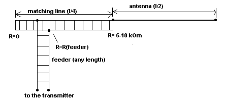
Fortunately in that time i have read about one very old, but not frequently used antenna - so called Zeppelin-antenna with a matched feeding. Classical design is presented below. As it can be seen, there is feeder with rather low impedance (~70-300 Ohm), and 1/4-wavelength matching line. From one end, this line is shortened, and here its impedance is just a zero (current is high, but voltage is low). Another end of this line is connected to the long wire, which has length exactly 1/2 wavelength. At this end, the impedance is very high (several kiloohms). That is why, a big voltage exists here during a transmission. Such impedance is quite suitable for a wire feeding, because a 1/2-wavelength wire has voltage maxima (high impedance) at the ends. The feeder from the transmitter with a specific impedance R(feeder) is connected to the matching line in the point, where impedance of the latter is equal to that of the feeder. Such point is usually located not so far from the closed end. If everything is done properly, feeder may have any length and SWR is closed to 1 in rather narrow band, central frequency of which is determined by the geometrical size of matching line and antenna.

-
This design can be used almost without change, but instead of symmetrical feeder coaxial cable can be used to connect the whole system to the unsymmetrical output of the transmitter. The using coaxial cable has also additional advantages- it is almost insensitive to the environment, can be placed everywhere and is very flexible.
-
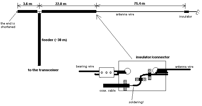
Such antenna with feeding 'from the end' is much more easy to make, that a simple dipole. Here, antenna conductor bears only itself, and this reduces the mechanical loading and thickness of the wire to be used. Also, you may use your window as one the point of antenna fixing. In this case, all the cable will be inside the room and could be tuned precisely in comfortable conditions. If the beginning of antenna is outside the apartment, most part of matching line can be used as the continuation of the feeding cable. On the next picture there is a design, that i implemented for using on 160 m.

-
All coaxial cables have 75 Ohm impedance, the antenna wire, as well as two bearing wires are made from very hard bimetallic insulated cable (outer diameter is about 3 mm). The most tricky part - the connector between cable and antenna - is shown on the picture. It should be noted, that voltage on it is quite high, so everything should be well insulated from each other. It is good to place this connector somewhere indoors (not far from window/hole), otherwise rains and snow may cause decreasing of insulation efficiency. This antenna uses a tuned line made from the coaxial cable, and for proper operation of the whole system the antenna should have the length equal to the l*0.95/2, and the coaxial line must resonate on the working frequency. It is a good idea, to connect the shortened end of the matching line to the ground to provide adequate safety and to reduce possible TV/RF interference while transmitting.
Tuning of the antenna
-
To achieve what was declared in the previous paragraph, first of all the precise length of the matching line should be determined. Theoretically, it should be equal to l/(4*sqrt(d)) (sqrt - SQuare RooT, d - dielectric constant of the insulator used in the coaxial cable). SQRT(d) value is typically about 1.52 for most cables, that is why, 'shortening coefficient' is about 0.66 (1/sqrt(d)). But the practical value will be a little different from that.
-
The lengths indicated on the picture are mine values, and they can be used as the approximate reference. To make your line resonate on the middle of the band (1890 kHz), you have to make the line about 1 m longer, that indicated on the picture (for example, 24 m). Then, connect the 1-2 kOhm resistor to the end of the line, and the transceiver trough SWR meter - to the feeder. Put some power into line and watch the SWR. If the line is completely out of resonance, SWR will be closed to infinity, and no power will be dissipated on the resistor. Then the frequency should be found, which gives the sharp minimum of the SWR. It should be somewhere 1750-1800 kHz. Here, the SWR should be no more than 1.5. After the resonance have been found, the end of the cable should be cut carefully in several steps, watching the resonance frequency each time. By the cutting, the resonance will be shifted up. After you achieve the desired frequency, your line is almost ready, and you can mount the antenna in the chosen place. The minimum of the SWR in mounted antenna is usually 10-15 kHz down, compared to the value achieved by the tuning. If the SWR in minimum is too great - the point of the feeder connection should be varied to achieve acceptable value (it means redistribution of the cable between short and long sections of the line - not easy task).
-
When i made the antenna by the way described, everything was OK, and i had a minimum of SWR at 1875 kHz (about 1.3), on the edges of the band SWR increased to 2.2-2.5, since this antenna is a narrow-band one. Compared to my previous dipole, which hanged on the low height along the building, this antenna exhibited much better transmission efficiency and higher signal/noise ratio while receiving. But unfortunately, nothing lasts forever, and this is not an exception. Having read the next section, you probably will understand, which problems are encountered by the ham operator in a big city like Moscow.
No comments:
Post a Comment