Keith WB2VUO
One of the problems with HF mobile operation, especially on 160, 80 or 40 Meters is antenna efficiency. The problem has been addressed in numerous publications for years, including, but not limited to the ARRL "Mobile Manual", the ARRL "Radio Amateurs Handbook", Editors & Engineers "Radio Handbook" and many others. If you are operating below 21 MHz,it is all but impossible to run a full-sized mobile antenna, so some sort of loading coil(s) will be needed.
Loaded antennas fall into three categories, Base-Loaded, Center-Loaded and Continuously-Loaded. The Base-Loaded antenna is the easiest to construct with the tools available to the "average" ham, but shows a lower efficiency than the other designs. Working with an 8-foot whip, typical of the stainless-steel whips sold for 11 or 10 Meter operation, a loading coil with an inductance of 1.1 uH to 350 uH would be needed for the 160 - 12 Meter bands, the lower the frequency, the larger the coil.
The radiation resistance of the 8-foot whip falls in a very low range, running from 0.08 ohms on the 160 Meter band to 16.1 ohms on the 12 Meter band as shown in the table below. If you have an ATU with a wide enough range, you COULD feed the whip directly with the ATU through a VERY short connection. At least one company (SGC) makes a mobile antenna system that does just this, mounting the ATU in a weatherproof box right at the antenna. It's kinda pricey though, running more than the price of some rigs. But, it CAN be done, 17 - 12 Meters for sure, and maybe even 20 Meters.
Now, the feedpoint impedance will NOT be the same as Rr. Ground losses, feedline losses and so on have to be factored in. The 10 Meter value is a good example for this point. An 8 foot whip, mounted to the average car/truck will show a feedpoint impedance of 30 - 45 ohms in the real world, and an acceptable SWR even without the use of an ATU. Mucho DX has been worked on the 10 Meter band with nothing more than this 8-foot whip, and before the advent of solid-state gear, the SWR was almost never considered. For that matter, my first HF mobile (a Heath HW-100) would handle a 3:1 load with the "stock" Pi-Net tuning. Tube rigs are/were very forgiving for loads.
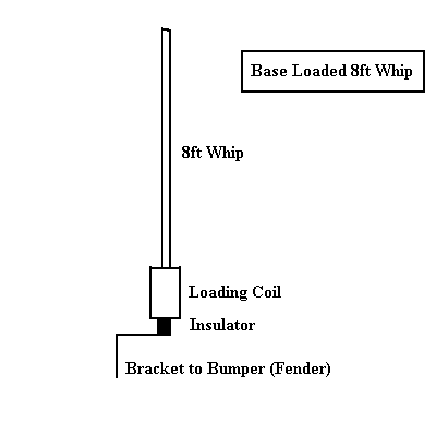
Here's a "sketch" of a Base-Loaded mobile antenna:

The base loading coil has to be mounted on a strong enough mount to take the normal flexing seen during mobile operation. Typically, the spring for the whip mount would be above the coil, allowing the whip to move without putting undue stress on the coil. Some commercial coils from the 50's had a bandswitch on coil allowing one to switch between the taps on the coil quickly.
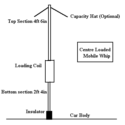
Here's a "sketch" of a Center-Loaded mobile antenna:
(The "Bugcatcher is a Center-Loaded antenna)

Typically, the bottom section is made of a larger diameter rigid section of tubing EMT, also known as conduit, makes a rugged makes a rugged bottom section, and the heavy galvanizing not only protects it from the elements, but allows one to solder directly to it for an improved connection. The zinc in the galvanized coating is a moderately good conductor, having a conductivity of 26 - 32% IACS. Copper, for comparison, has a conductivity of 100% IACS. Only silver is better.
While pure aluminum has a conductivity of 61% IACS, the common alloys are in the 28 - 35% IACS conductivity range, so galvanized steel is very close to aluminum for RF purposes, and is much stronger (but also much heavier). For RF applications, only the zinc coating need be considered due to the skin effect.
NOTE: The "Hat" is a capacity hat, and is optional. It WILL greatly improve the performance on the 160 - 40 Meter bands as it reduces the size (and losses) of the loading coil.
No comments:
Post a Comment